In this tutorial, we are going to use DE0-Nano to read the voltage across a potentiometer. Then DE0-Nano will send data to Raspberry Pi 4B.
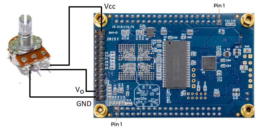
Step 1: Connect the potentiometer to DE0-Nano
Step 2: Open the ADC example
e.g. C:\DE0\DE0-Nano_v.1.2.8_SystemCD\Demonstration\DE0_NANO_ADC
Make sure that the ADC and GPIO ports are included in the Pin Planner
Step 3: Edit the DE0-Nano.v as follows. The GPIO_0[10:3] will be used to communicate to Raspberry Pi later.
module DE0_NANO(
//////////// CLOCK //////////
CLOCK_50,
//////////// LED //////////
LED,
//////////// KEY //////////
KEY,
//////////// SW //////////
SW,
//////////// SDRAM //////////
DRAM_ADDR,
DRAM_BA,
DRAM_CAS_N,
DRAM_CKE,
DRAM_CLK,
DRAM_CS_N,
DRAM_DQ,
DRAM_DQM,
DRAM_RAS_N,
DRAM_WE_N,
//////////// EPCS //////////
EPCS_ASDO,
EPCS_DATA0,
EPCS_DCLK,
EPCS_NCSO,
//////////// Accelerometer and EEPROM //////////
G_SENSOR_CS_N,
G_SENSOR_INT,
I2C_SCLK,
I2C_SDAT,
//////////// ADC //////////
ADC_CS_N,
ADC_SADDR,
ADC_SCLK,
ADC_SDAT,
//////////// 2x13 GPIO Header //////////
GPIO_2,
GPIO_2_IN,
//////////// GPIO_0, GPIO_0 connect to GPIO Default //////////
GPIO_0,
GPIO_0_IN,
//////////// GPIO_1, GPIO_1 connect to GPIO Default //////////
GPIO_1,
GPIO_1_IN
);
//////////// CLOCK //////////
input CLOCK_50;
//////////// LED //////////
output [7:0] LED;
//////////// KEY //////////
input [1:0] KEY;
//////////// SW //////////
input [3:0] SW;
//////////// SDRAM //////////
output [12:0] DRAM_ADDR;
output [1:0] DRAM_BA;
output DRAM_CAS_N;
output DRAM_CKE;
output DRAM_CLK;
output DRAM_CS_N;
inout [15:0] DRAM_DQ;
output [1:0] DRAM_DQM;
output DRAM_RAS_N;
output DRAM_WE_N;
//////////// EPCS //////////
output EPCS_ASDO;
input EPCS_DATA0;
output EPCS_DCLK;
output EPCS_NCSO;
//////////// Accelerometer and EEPROM //////////
output G_SENSOR_CS_N;
input G_SENSOR_INT;
output I2C_SCLK;
inout I2C_SDAT;
//////////// ADC //////////
output ADC_CS_N;
output ADC_SADDR;
output ADC_SCLK;
input ADC_SDAT;
//////////// 2x13 GPIO Header //////////
inout [12:0] GPIO_2;
input [2:0] GPIO_2_IN;
//////////// GPIO_0, GPIO_0 connect to GPIO Default //////////
output [33:0] GPIO_0;
input [1:0] GPIO_0_IN;
//////////// GPIO_1, GPIO_1 connect to GPIO Default //////////
inout [33:0] GPIO_1;
input [1:0] GPIO_1_IN;
wire wSPI_CLK;
wire wSPI_CLK_n;
reg [33:0] GPIO_0;
reg [7:0] PWM_adj;
reg [8:0] PWM_width;
//=======================================================
// Structural coding
//=======================================================
SPIPLL U0 (
.inclk0(CLOCK_50),
.c0(wSPI_CLK),
.c1(wSPI_CLK_n)
);
ADC_CTRL U1 (
.iRST(KEY[0]),
.iCLK(wSPI_CLK),
.iCLK_n(wSPI_CLK_n),
.iGO(KEY[1]),
.iCH(SW[2:0]),
.oLED(LED),
.oDIN(ADC_SADDR),
.oCS_n(ADC_CS_N),
.oSCLK(ADC_SCLK),
.iDOUT(ADC_SDAT)
);
always @(posedge CLOCK_50)
begin
GPIO_0[10:3] <= LED[7:0];
end
endmodule
Step 4: As "Analog_In0" is used, adjust the DIP switch as follows

Step 5: Compile and upload the sof file via the "Programmer" option. Then press the Key Button 1 in DE0-Nano. When the potentiometer is rotated, the onboard LED should light up accordingly.
Step 6: Use 8 female jumper wires to connect DE0-Nano to Raspberry Pi 4B.
DE0-Nano <=> RPi 4B
GPIO_0[3] <=> GPIO 17
GPIO_0[4] <=> GPIO 27
GPIO_0[5] <=> GPIO 22
GPIO_0[6] <=> GPIO 23
GPIO_0[7] <=> GPIO 24
GPIO_0[8] <=> GPIO 25
GPIO_0[9] <=> GPIO 16
GPIO_0[10] <=> GPIO 26
Step 7: Prepare an 8-bit truth table
You may open excel and set A1, B1, C1, D1, E1, F1, G1, H1 cells to 0.
Type the following formula in H2 cell.
=IF(MOD(ROW()-ROW($H$1),POWER(2, ((COLUMN() - COLUMN($H$1)) * -1) + 1)) >= (POWER(2, ((COLUMN() - COLUMN($H$1)) * -1) + 1) / 2),1,0)
Drag the "+" logo from H2 cell to the others.
Copy the 2048 elements in truth table and save the file as "8bit_truthtable.txt"
Step 8: Write Python code in Raspberry Pi.
import RPi.GPIO as GPIO
import time
binary=[0]*256;
with open("8bit_truthtable.txt") as f:
data = f.readlines();
for i in range(0,256):
binary[i] = data[i].split();
pinA=26; #the most significant bit
pinB=16;
pinC=25;
pinD=24;
pinE=23;
pinF=22;
pinG=27;
pinH=17; #the least significant bit
for i in range(8):
globals()[f'diff{i}']=[0]*256;
GPIO.setmode(GPIO.BCM)
GPIO.setwarnings(False)
GPIO.setup(pinA,GPIO.IN)
GPIO.setup(pinB,GPIO.IN)
GPIO.setup(pinC,GPIO.IN)
GPIO.setup(pinD,GPIO.IN)
GPIO.setup(pinE,GPIO.IN)
GPIO.setup(pinF,GPIO.IN)
GPIO.setup(pinG,GPIO.IN)
GPIO.setup(pinH,GPIO.IN)
while True:
A = GPIO.input(pinA)
B = GPIO.input(pinB)
C = GPIO.input(pinC)
D = GPIO.input(pinD)
E = GPIO.input(pinE)
F = GPIO.input(pinF)
G = GPIO.input(pinG)
H = GPIO.input(pinH)
#Subtracted ADC reading by each of the row in truth table.
#If these two values the same, the digital level is marked and compared
for i in range(0,256):
diff0[i] = A-int(binary[i][0]);
diff1[i] = B-int(binary[i][1]);
diff2[i] = C-int(binary[i][2]);
diff3[i] = D-int(binary[i][3]);
diff4[i] = E-int(binary[i][4]);
diff5[i] = F-int(binary[i][5]);
diff6[i] = G-int(binary[i][6]);
diff7[i] = H-int(binary[i][7]);
if(diff0[i]==0 and diff1[i]==0 and diff2[i]==0 and diff3[i]==0 and diff4[i]==0 and diff5[i]==0 and diff6[i]==0 and diff7[i]==0):
print(i);
time.sleep(0.1);
Step 9: Press F5 to run the Python script. When the potentiometer is rotated, the digital reading should vary between 0 and 255.


Comments
Post a Comment