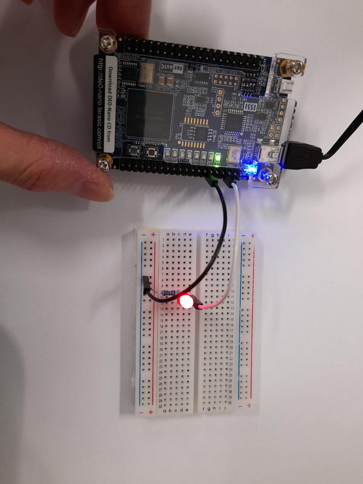
In this tutorial, we are going to write Verilog code to read the accelerometer along the x and y-axis in FPGA (DE0-Nano). A LED and 220-ohm resistor are connected through a GPIO port. When you rotate the FPGA, the light intensity of the LED should vary continuously.
 |
| Terasic |
Step 1: Build the circuit below

Step 2: Open the example "DE0_NANO_GSensor" in Terasic CD. Follow the DE0-Nano_User_Manual.pdf to add the GPIO_0_D and GPIO_0_IN in the pin planner.

Step 3: Paste the following code to DE0-NANO.v
module DE0_NANO(
//////////// CLOCK //////////
CLOCK_50,
//////////// LED //////////
LED,
//////////// KEY //////////
KEY,
//////////// Accelerometer and EEPROM //////////
G_SENSOR_CS_N,
G_SENSOR_INT,
I2C_SCLK,
GPIO_0_D,
GPIO_0_IN,
I2C_SDAT
);
//////////// CLOCK //////////
input CLOCK_50;
//////////// LED //////////
output [7:0] LED;
//////////// KEY //////////
input [1:0] KEY;
//////////// Accelerometer and EEPROM //////////
output G_SENSOR_CS_N;
input G_SENSOR_INT;
output I2C_SCLK;
inout I2C_SDAT;
inout [33:0] GPIO_0_D;
input [1:0] GPIO_0_IN;
//=======================================================
// REG/WIRE declarations
//=======================================================
wire dly_rst;
wire spi_clk, spi_clk_out;
wire [15:0] data_x;
wire [15:0] data_y;
wire [15:0] data_z;
reg [7:0] GPIO_0_D;
//=======================================================
// Structural coding
//=======================================================
//Reset
reset_delay u_reset_delay (
.iRSTN(KEY[0]),
.iCLK(CLOCK_50),
.oRST(dly_rst));
// PLL
spipll u_spipll (
.areset(dly_rst),
.inclk0(CLOCK_50),
.c0(spi_clk), // 2MHz
.c1(spi_clk_out)); // 2MHz phase shift
// Initial Setting and Data Read Back
spi_ee_config u_spi_ee_config (
.iRSTN(!dly_rst),
.iSPI_CLK(spi_clk),
.iSPI_CLK_OUT(spi_clk_out),
.iG_INT2(G_SENSOR_INT),
.oDATA_L(data_x[7:0]), //higher sensitivity
oDATA_L(data_x[10:0],oDATA_H(data_x[15:11]) tune
.oDATA_H(data_x[15:8]),
.SPI_SDIO(I2C_SDAT),
.oSPI_CSN(G_SENSOR_CS_N),
.oSPI_CLK(I2C_SCLK));
//LED
led_driver u_led_driver (
.iRSTN(!dly_rst),
.iCLK(CLOCK_50),
.iDIG(data_x[9:0]),
.iG_INT2(G_SENSOR_INT),
.oLED(LED));
always @(posedge CLOCK_50)
begin
if(LED[3]!=1'b0 && LED[4]!=1'b0) //tilt x-axis
GPIO_0_D[3] <= 1'b0;
else
GPIO_0_D[3] <= 1'b1;
end
endmodule
Step 4: Paste the following code to spi_ee_config.v
module spi_ee_config (
iRSTN,
iSPI_CLK,
iSPI_CLK_OUT,
iG_INT2,
oDATA_L,
oDATA_H,
SPI_SDIO,
oSPI_CSN,
oSPI_CLK);
`include "spi_param.h"
//=======================================================
// PORT declarations
//=======================================================
// Host Side
input iRSTN;
input iSPI_CLK, iSPI_CLK_OUT;
input iG_INT2;
output reg [SO_DataL:0] oDATA_L;
output reg [SO_DataL:0] oDATA_H;
// SPI Side
inout SPI_SDIO;
output oSPI_CSN;
output oSPI_CLK;
//=======================================================
// REG/WIRE declarations
//=======================================================
reg [3:0] ini_index;
reg [SI_DataL-2:0] write_data;
reg [SI_DataL:0] p2s_data;
reg spi_go;
wire spi_end;
wire [SO_DataL:0] s2p_data;
reg [SO_DataL:0] low_byte_data;
reg spi_state;
reg high_byte;
reg read_back;
reg clear_status, read_ready;
reg [3:0] clear_status_d;
reg high_byte_d, read_back_d;
reg [IDLE_MSB:0] read_idle_count;
//=======================================================
// Sub-module
//=======================================================
spi_controller u_spi_controller (
.iRSTN(iRSTN),
.iSPI_CLK(iSPI_CLK),
.iSPI_CLK_OUT(iSPI_CLK_OUT),
.iP2S_DATA(p2s_data),
.iSPI_GO(spi_go),
.oSPI_END(spi_end),
.oS2P_DATA(s2p_data),
.SPI_SDIO(SPI_SDIO),
.oSPI_CSN(oSPI_CSN),
.oSPI_CLK(oSPI_CLK));
//=======================================================
// Structural coding
//=======================================================
// Initial Setting Table
always @ (ini_index)
case (ini_index)
0 : write_data = {THRESH_ACT,8'h20};
1 : write_data = {THRESH_INACT,8'h03};
2 : write_data = {TIME_INACT,8'h01};
3 : write_data = {ACT_INACT_CTL,8'h7f};
4 : write_data = {THRESH_FF,8'h09};
5 : write_data = {TIME_FF,8'h46};
6 : write_data = {BW_RATE,8'h09}; // output data rate : 50 Hz
7 : write_data = {INT_ENABLE,8'h10};
8 : write_data = {INT_MAP,8'h10};
9 : write_data = {DATA_FORMAT,8'h40};
default: write_data = {POWER_CONTROL,8'h08};
endcase
always@(posedge iSPI_CLK or negedge iRSTN)
if(!iRSTN)
begin
ini_index <= 4'b0;
spi_go <= 1'b0;
spi_state <= IDLE;
read_idle_count <= 0; // read mode only
high_byte <= 1'b0; // read mode only
read_back <= 1'b0; // read mode only
clear_status <= 1'b0;
end
// initial setting (write mode)
else if(ini_index < INI_NUMBER)
case(spi_state)
IDLE : begin
p2s_data <= {WRITE_MODE, write_data};
spi_go <= 1'b1;
spi_state <= TRANSFER;
end
TRANSFER : begin
if (spi_end)
begin
ini_index <= ini_index + 4'b1;
spi_go <= 1'b0;
spi_state <= IDLE;
end
end
endcase
// read data and clear interrupt (read mode)
else
case(spi_state)
IDLE : begin
read_idle_count <= read_idle_count + 1;
if (high_byte) // multiple-byte read
begin
if(read_idle_count%2 == 0)
begin
p2s_data[15:8] <={READ_MODE,X_HB};
end
if(read_idle_count%2 != 0)
begin
p2s_data[15:8] <={READ_MODE,Y_HB};
end
read_back <= 1'b1;
end
else if (read_ready)
begin
if(read_idle_count%2 == 0)
begin
p2s_data[15:8] <={READ_MODE, X_LB};
end
if(read_idle_count%2 != 0)
begin
p2s_data[15:8] <={READ_MODE, Y_LB};
end
read_back <= 1'b1;
end
else if (!clear_status_d[3]&&iG_INT2 || read_idle_count[IDLE_MSB])
begin
p2s_data[15:8] <= {READ_MODE, INT_SOURCE};
clear_status <= 1'b1;
end
if (high_byte || read_ready || read_idle_count[IDLE_MSB] || !clear_status_d[3]&&iG_INT2)
begin
spi_go <= 1'b1;
spi_state <= TRANSFER;
end
if (read_back_d) // update the read back data
begin
if (high_byte_d)
begin
oDATA_H <= s2p_data;
oDATA_L <= low_byte_data;
end
else
low_byte_data <= s2p_data;
end
end
TRANSFER : begin
if (spi_end)
begin
spi_go <= 1'b0;
spi_state <= IDLE;
if (read_back)
begin
read_back <= 1'b0;
high_byte <= !high_byte;
read_ready <= 1'b0;
end
else
begin
clear_status <= 1'b0;
read_ready <= s2p_data[6];
read_idle_count <= 0;
end
end
end
endcase
always@(posedge iSPI_CLK or negedge iRSTN)
if(!iRSTN)
begin
high_byte_d <= 1'b0;
read_back_d <= 1'b0;
clear_status_d <= 4'b0;
end
else
begin
high_byte_d <= high_byte;
read_back_d <= read_back;
clear_status_d <= {clear_status_d[2:0], clear_status};
end
endmodule
Step 5: Compile the code and upload the sof file via the use of "Programmer". The LED through GPIO_0_D[3] lights up when the FPGA is rotated.

Comments
Post a Comment